-40%
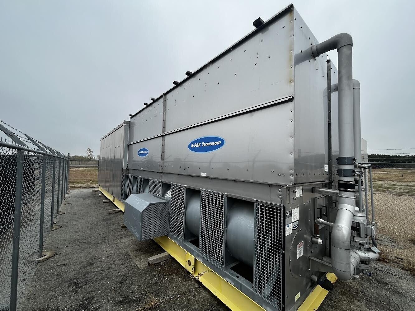
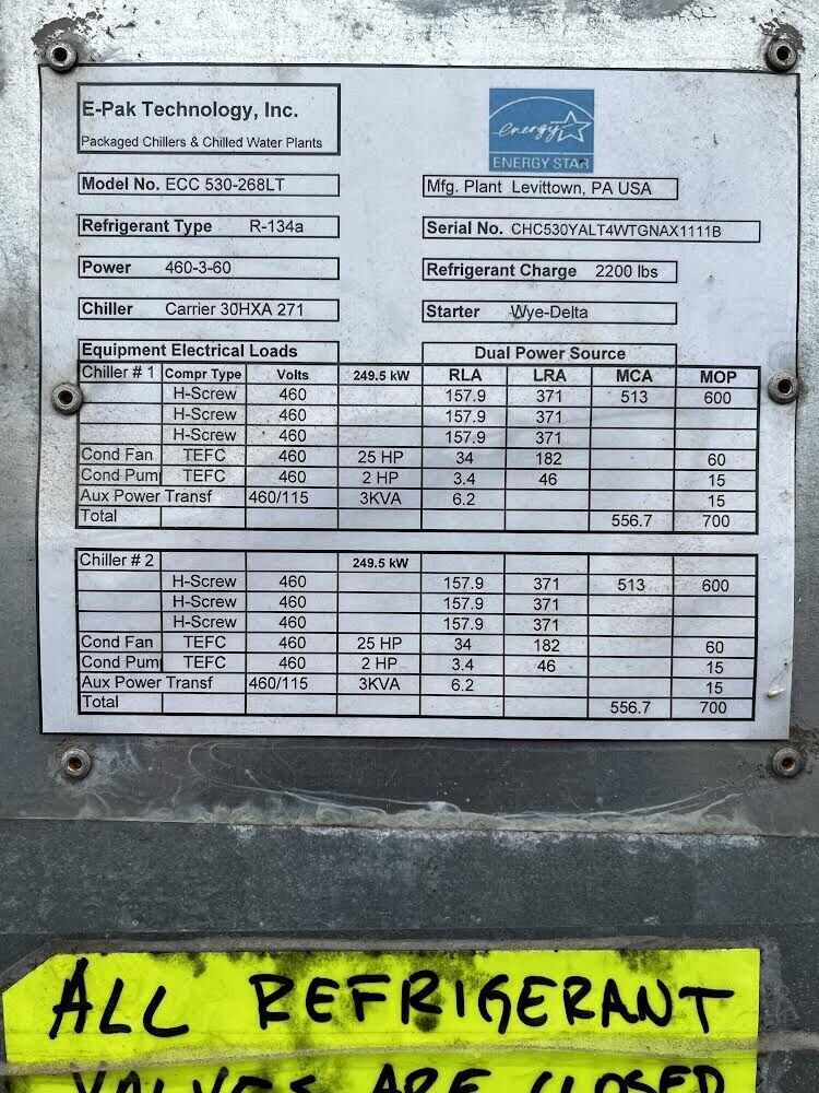
E-Pak Evaporative Cooled Flooded Evaporator Screw Compressor Packaged Chiller
$ 132000
- Description
- Size Guide
Description
EVAPORATIVE COOLED FLOODED EVAPORATOR SCREW COMPRESSOR PACKAGED CHILLERSGENERAL
CAPACITIES FROM 80 TONS TO 535 TONS
FLOODED EVAPORATOR CLEANABLE WATER SIDE COOLER TUBES
LOW MCA ALLOWS MORE CAPACITY ON SMALLER ELECTRICAL SERVICE REFRIGERANT CIRCUITS
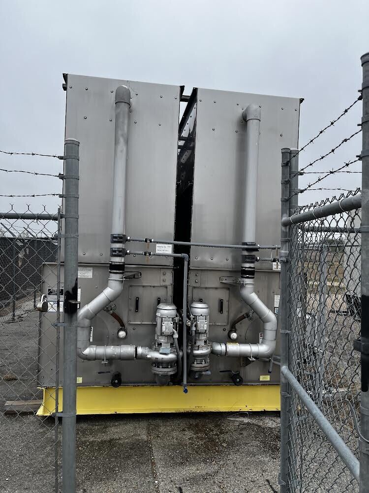
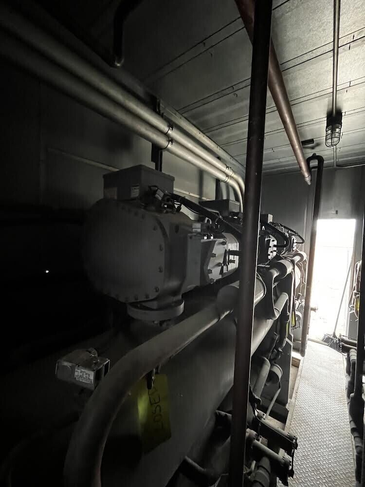
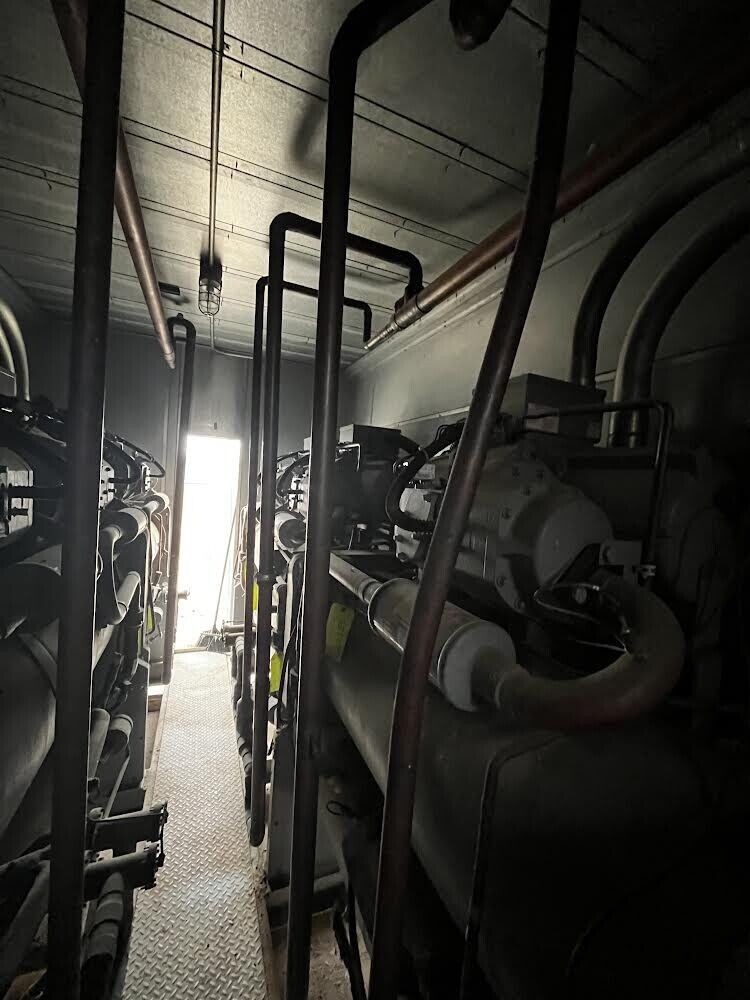
The chiller is an evaporative cooled chiller completely packaged on a self-supporting steel frame with all refrigerant piping and interconnecting power and control wiring installed and tested by the manufacturer prior to shipment.
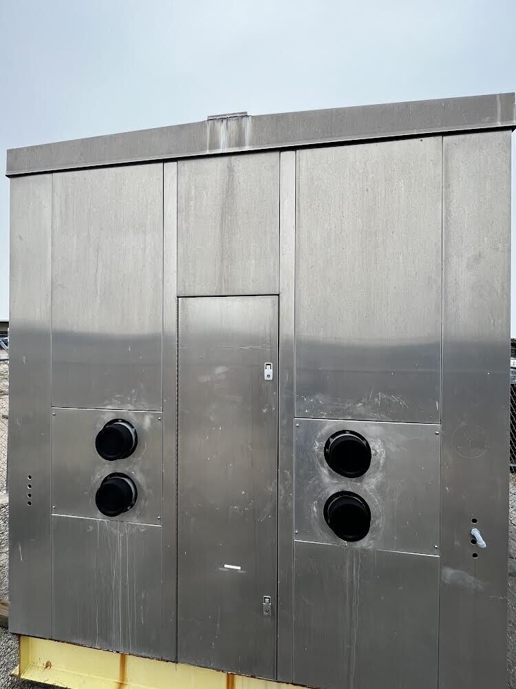
The chiller is suitable for outdoor installa- tion with all chiller components enclosed in a protective aluminum weather housing and all unprotected system components are suitable for outdoor operation.
The chiller has a minimum system energy efficiency ratio (EER) including compres- sors, condenser fan(s), condenser pump and control power and a system energy consumption rate as specified in the chiller equipment schedule.
The chiller performance is rated in accordance with ARI standard 590.
COMPRESSOR MOTOR
The chiller is equipped with multiple semihermetic, gear driven helical rotary screw compressors with each compressor installed in an independent refrigerant circuit.
Each compressor has liquid and discharge service stop valve (suction stop valve optional); internal and external oil filters; internal pressure relief; low oil flow pro- tection; double mesh suction inlet strain- ers; electrically actuated step unloaders; rubber-in-shear isolation mountings and shall operate with HFC-134a refrigerant.
EVAPORATOR (R-134A)
FLOODED:
Each evaporator is dual circuited shell
& tube design with seamless internally enhanced copper tubes roller expanded into the tubesheets. Designed, tested and stamped in accordance with ASME pres- sure vessel code for refrigerant side work- ing pressure of 220 psig and a maximum fluid side pressure of 320 psig.
The water side heads are removable for alternating left hand or right hand water connection and tubes are mechanically cleanable. Each evaporator contains temperature sensors to control leaving fluid temperature, low refrigerant temper- ature freeze protection, and is equipped with vent and drain connections and insulated with 3/4-inch closed cell insulation with a .28 K valve.
Low ambient applications (optional) are equipped with heat tracing system to protect against evaporator freeze up.
The chiller has multiple independent refrigeration circuits. Each circuit includes an oil separator which is tested and stamped in accordance with ASME code for a working pressure of 320 psig, dis- charge service valves, replaceable core filter driers, combination moisture indica- tor sight glass, electronic expansion valve, charging valves and insulated suction lines and low side relief valves are provided
for each circuit (300 psi). Each refrigerant circuit is pressure tested, evacuated
and shipped with a complete charge
of compressor oil and a holding charge
at 30 psi of refrigerant HFC-134a.
CONDENSER
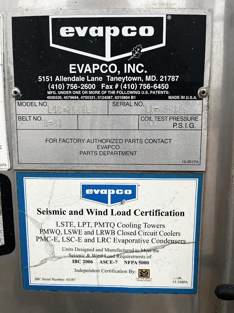
The chiller unit is equipped with a forced draft multi-circuit evaporative condenser which is selected to provide the heat of rejection capacity required by the chiller at the specified condition.
PAN & CASING
The pan and casing is constructed of G-235 hot dip galvanized steel.
The pan/fan section includes fan(s) with motors and drives mounted and aligned at the factory. The motors and weather safety shields are removed for shipping to be reinstalled in the field.
Standard pan accessories include circular access doors, stainless steel strainers, waste water bleed line with adjustable valve and brass make-up valve with an unsinkable foam filled plastic float.
CENTRIFUGAL FANS
The fans are forward curved centrifugal type of hot dip galvanized construction. The fans are factory installed to the pan/ fan section, statically and dynamically balanced. The fans are mounted on either a solid or hollow steel shaft with forged journal bearings. The fan shaft is support- ed by heavy duty, self-aligning bearings with cast-iron housings and lubrication fittings for maintenance.
The fan drive(s) are V-Belt type with taper lock sheaves designed for 150% of the motor nameplate horsepower. The drive(s) are mounted and aligned at the factory.
FAN MOTOR
Totally enclosed fan cooled motor(s) with a 1.15 service factor (inverter duty type motor with a 1.25 service factor when used in conjuction with a variable fre- quency drive) is furnished suitable for outdoor service. Motor(s) are mounted on an adjustable base. (See Fan Motor, page 20.)
HEAT TRANSFER COIL
The coil(s) are constructed entirely of prime surface steel, encased in steel framework with the entire assembly hot- dip galvanized after fabrication. Coil(s) are designed with sloping tubes for free drainage of liquid refrigerant and tested to 350 psig air pressure under water. Each coil circuit is sized for the heat
of rejection capacity of each individual refrigerant circuit. The coil features ellipti- cal tube design which permits greater water loading, lower air flow resistance and higher heat transfer efficiency.
SUBCOOLING COIL
The subcooling coil, when required, is
also prime surface steel, encased in a steel framework with the entire assembly hot dip galvanized after fabrication. The refrigerant Inlet line to the subcooler is trapped to maintain a liquid seal to the subcooler, which trap is also furnished with a liquid indicator sight glass. These coils are designed with sloping tubes for free drainage of refrigerant and tested to 350
psig air pressure under water. Each coil circuit is sized to provide the necessary sub- cooling required at each expansion valve.
WATER DISTRIBUTION SYSTEM
The system provides a water flow rate
of not less than 6 GPM over each square foot of unit face area to ensure proper flooding of the coil. The spray header is constructed of schedule 40, PVC pipe for corrosion resistance. All spray branches are removable and include a threaded end plug for cleaning. The water is distributed over the entire coil surface
by precision molded ABS spray nozzles (1" x 1/2" orifice) with internal anti- sludge rings to eliminate clogging. Nozzles are threaded into spray header to provide easy removal for maintenance.
WATER RECIRCULATION PUMP
The pump is a close-coupled, bronze fit- ted, centrifugal type with mechanical seal, installed vertically at the factory to allow free drainage on shut down. The totally enclosed motor is furnished suitable for outdoor service.
ELIMINATORS
The eliminators are constructed entirely
of PVC that has been specially treated to resist ultra-violet light. Assembled in easily handled sections, the eliminator blades are spaced on 1-inch centers and incor- porate three changes in air direction to assure removal of entrained moisture
from the discharge air stream. They have a hooked leaving edge to direct the dis- charge air away from the fans to mini- mize recirculation.
FINISH
All pan and casing materials are con- structed of G-235 heavy gauge mill hot- dip galvanized steel for maximum protec- tion against corrosion. During fabrication, all panel edges are coated with a
95% pure zinc-rich compound.
CHILLER CONTROL SYSTEM
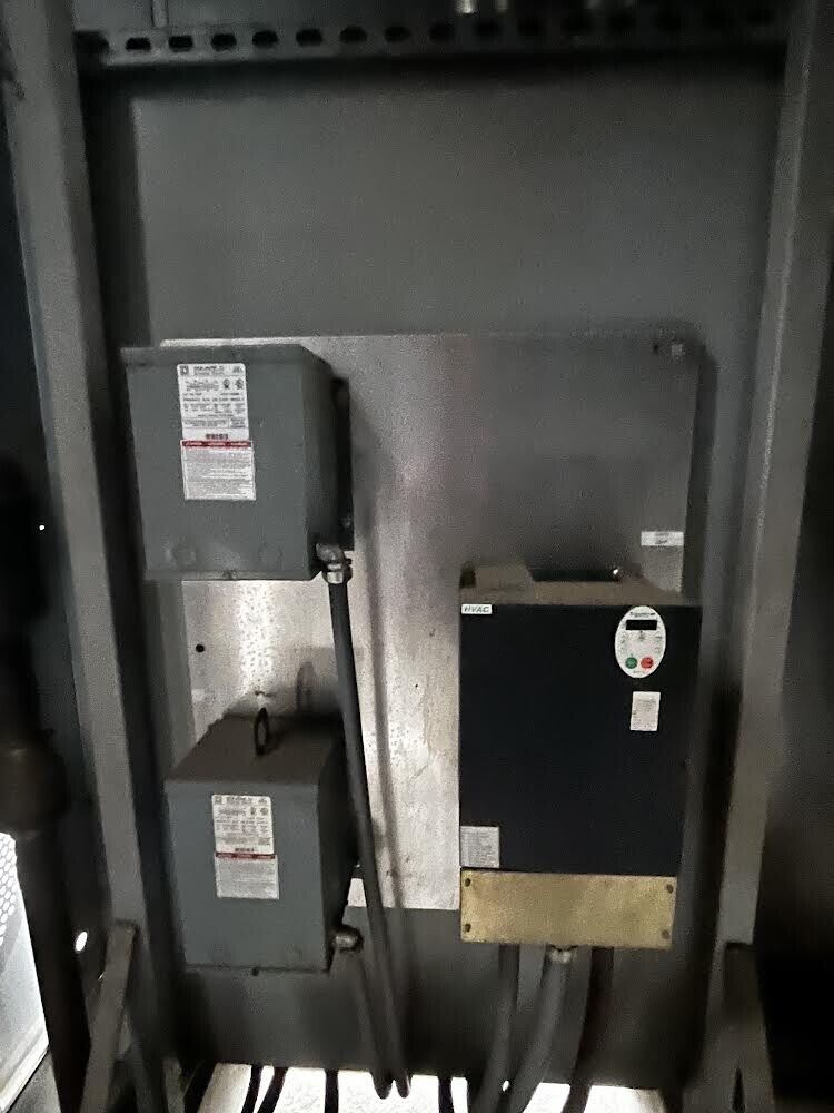
The chiller is equipped with a fully inte- grated microprocessor control system which includes all controls and sensors factory mounted and tested prior to shipment. The standard microprocessor |is equipped with a 2-Line 14 character per line diagnostic display with data entry control key pad. (A 16 line,
40 character per line expanded display is an available option).
The microprocessor control system pro- vides all control functions including start up and shut down, anti-recycle logic, automatic lead/lag compressor starting/ leaving chilled fluid temperature control with return fluid sensing and evaporator freeze protection. The microprocessor is capable of limiting the chilled fluid pull down rate at start up to an adjustable range of 0.2°F to 2.0°F per minute to prevent demand spikes at start up and provide seven day time scheduling of condenser pumps, chilled water pumps and chillers.
DIAGNOSTICS
The microprocessor display module is capable of displaying set points, time, system status including temperatures, pressures, percent loading and daily alarm or alert conditions.
The control module is capable of displaying the output of a run test to verify operation of every switch, sensor, potentiometer and compressor before chiller is started.
SAFETIES
The control systems provides the chiller unit with protection against the following:
Loss of Refrigerant Charge Ground Current
Reverse Rotation
Thermal Overload
Low Chilled Fluid Temperature High Pressure
Low Oil Pressure
Electrical Overload
Voltage Imbalance Loss of Phase
